Saturday, February 19, 2011

Digital thermometer modification: halfway through


Expect loads of pictures!

After I got that idea about modifying a digital thermometer I couldn't stop thinking about it. So I decided to do it right away. First I had to disassemble the thermometer. The procedure is simple and easy, only tool needed is a small flat screwdriver to press some pins and the case opens. The insides can be seen in the picture below.

Digital thermometer parts
1 - two LR44 button batteries; 2 - LCD screen; 3 - case, upper half; 4 - plastic spacer between the LCD screen and the circuit board;
5 - circuit board; 6 - case, bottom half

Next I had to find the correct pair of connections that I could use to determine the temperature. After some testing I found out that I have to connect the + source to the connection marked on the picture below.

the circuit board closeup

Once I soldered all the wires and a female 3.5 jack connector I reassembled everything and the physical work was done. Results:

wiring completed

multimeter measures 1.42 V at 30.8 °C
Multimeter reading is in Volts.
After some experimenting I found out that when temperature increases, voltage drops.

As you can see on the multimeter, I can measure the voltage without any problems. The maximum voltage would be 1.50 V so there is no harm to the computer.
The problem occours when I actually plug the jack into the computer Line-In. Suddenly the voltage drops to about 5 mV and there is no way to increase it back to the previous normal level. Voltage measurement of the computer's Line-In input:

oscilloscope measurement of the Line-In voltage reads 6 mV
No explanation for this yet


If you have any suggestions what might be causing the voltage drop and how to fix it, please let me know.

Digital thermometers


I've been sick and didn't have much strength to think or write. But today I saw some of my chilli plants have sprouted (yeah, I also grow chillis) and I noticed that the temperature in the room was over 33 °C when there was sun shining.
And it got me thinking that every time that I want to do a temperature measurement, I have to look at the tiny LCD display of the digital thermometer, write down the temperature on a piece of paper, and then look at my watch and write down the time the temperature was taken. That's because I only have the cheapest thermometers available, those for $2 off ebay.

a cheap digital thermometer
This is so cheap, you should buy hundreds!

So I decided to do something about it. I want to modify one of these thermometers so I can connect it to my computer and record temperatures automatically. I am not sure how I'm going to do it yet. The most simple option would be to just connect it to the Line-In audio jack and then record the raw voltage input. A more advanced option would of course be the USB connector, but this will most likely require some kind of a driver.

Tuesday, February 15, 2011

A discussion about the flaws of my experiment


I talked about my experiment on a science-oriented forum yesterday and we discussed the possible flaws of my experiment. Several interesting improvements are suggested. I will post here the highlights of the other users' comments and my replies to them.

One of them wrote:
"I'm guessing you did this:
You dripped some water from your fingers directly onto the surface of the peltier device, and it froze.

You then put some water in that small beaker, and place the beaker on the surface of the device. Well, unless your device surface and beaker bottom are absolutely flat, you're going to get somewhat poor thermal conduction. You could coat the interface with some of that thermally conductive paste if you are looking for a better result. It's the same white stuff you may see between the heatsink and the junction on the other side."
True, I first dripped a couple of drops from a 10 mL medical syringe directly onto the surface. This is the most efficient method, but only allows the cooling of very small volumes.
When I tried to freeze the water in the glass beaker, the surface of the beaker is not flat and the thermal conductivity between the beaker and the cooler was poor. Thermal paste would improve the results a bit, but as the glass itself has a poor thermal conductivity, It would still be inefficient. I think a better solution would be that instead of the beaker I use a smaller container with a thin bottom and made of some material with better thermal conductivity, for example aluminium or copper. Thermal paste could be applied as well if needed.


Another point was the inefficiency of the heatsink.
"Is there a fan on the heatsink on the hot side? Are you using that fan? Is it free to move air?"
"Well if I understand your setup photo, your fan is sitting directly on the table surface. That limits its ability to move air."
There is a fan on the heatsink (that I got from an old computer lying in my attic), but a rather small one. I think it has 6 cm in diameter at most. During the experiment  the heatsink was put on top of a large tube that allowed plenty of cool air to reach the heatsink. I am looking for a better heatsink but I don't want to spend money for it, because my resources are limited.

Monday, February 14, 2011

Peltier cooler: DIY part one


So I finally got a peltier cooler from ebay last week. You can buy one for about $5 (depending on postage it could be more). I dropped some water on it while being connected to my PSU (14.5V, 23A) and it froze almost instantly. However, when I tried a larger amount of water (13 mL, a volume of one ice-cube), it never froze. The problem is in the cooler block on the other side, because it's not efficient enough. The whole system overheats after a couple of minutes.

Here is a picture of the setup of the first experiment (PSU not visible):
peltier cooler with heat sink attached
(click to view in full size)

And here is a temperature/time plot of the experiment. Note that temperature is in degrees Celsius.

temperature plot
(again, click to view in full size)

Sunday, February 13, 2011

Hell goo 2


And here is the second blog from the awesome Thijs Boerma.


http://hellgoo2.blogspot.com/


Make sure to check it out if you liked his original project mentioned earlier. I sure can't wait to see what he's come up with this time around. I hope it's even more gross than before.

Peltier coolers: how it all began


I was browsing youtube one day because I was annoyed with my freezer taking 2 hours to turn water to ice. I came along a lot of videos featuring so called "Peltier coolers", which amazed me instantly. For example see this video:

My current project: Peltier cooler


So a little background introduction at first. What are peltier coolers?

Wikipedia says:
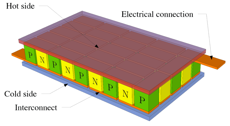
"Thermoelectric cooling uses the Peltier effect to create a heat flux between the junction of two different types of materials. A Peltier cooler, heater, or thermoelectric heat pump is a solid-state active heat pump which transfers heat from one side of the device to the other side against the temperature gradient (from cold to hot), with consumption of electrical energy. Such an instrument is also called a Peltier device, Peltier heat pump, solid state refrigerator, or thermoelectric cooler (TEC). The Peltier device is a heat pump: When DC current runs through it, heat is moved from one side to the other. Therefore it can be used either for heating or for cooling (refrigeration), although in practice the main application is cooling. It can also be used as a temperature controller that either heats or cools."
Here's a diagram of a thermoelectric cooler.

(click on the image to view labels)